
With half the people in the house under the weather – and myself not that great, just slightly better than them right now – I’m sitting home looking at my desks and waiting for the impending storm outside. So I decided to challenge myself to get the APRS computer rebuilt before the storm arrives and I want it online and fully functional. On the second write of the OS to the new SD card since apparently the power supply I was using was a bit underpowered and it kept rebooting, so who knows if anything got hosed in all that. Rather start over than find out a month from now something is horribly broken under the hood.
Category Archives: Electronics
No, No… Canned Air!
I’m going, I’m going
–Canned Heat, “Going Up The Country”
Where the water tastes like wine
I’m going where the water tastes like wine
We can jump in the water
Stay drunk all the time

I don’t remember the last time I bought canned air dusters, or canned air (not to be confused with Perri-Air), but I do remember when I took out the last unused one it felt half empty. And that one just about ran out, so I needed to get more. I don’t use it often, obviously, but part of that was self-fulfilling – if I use it up, I don’t have any, so I tend to not use it unless I don’t have other options. I do have an electronics safe vacuum as well, which is wonderful, but sometimes you just need to blast the crap out of somewhere.
So I went on a search to see if there was a good alternative yet; years ago I bought this small can with a valve on the bottom and a bundled air compressor that was obnoxiously noisy, with the promise I could just refill it when I needed to. In practice, it worked for a few seconds and quickly lost useful pressure, and then you had to endure the noise of refilling it. That was, in my mind, not a viable option.
I then found that quite a few companies make electric (really battery) powered handheld devices for this purpose, and after enduring a few videos on the topic (and deleting them from my history, because otherwise every freaking video is a review of another one of these things), I found one from Wolfbox which had the highest recommendations from various places, good specs, and a decent price. But before buying it, I found there’s a newer version, the MF200, which is about the same price when I placed the order but has the ability to get additional batteries for a longer run time and swap them around. While I don’t anticipate needing that functionality, it does sound interesting, plus the unit was a little beefier than the original (and can set flat on its base, so I kinda preferred the ergonomics too). Add to cart, place order, research complete!
Last night I tested it, and from across the room I just gave it a quick burst and about two seconds later the youngest reeled back in his chair from the blast of air he got hit with. Definitely has the power that a can of air would have, and my hand doesn’t start to freeze when using it either which makes it more useful since I don’t have to stop and wait for the can to warm up and the liquid inside to boil off and pressurize things again. This afternoon when he finished vacuuming and took the canister out to dump it, I grabbed the filter from under the canister and took it to the porch. Maybe a minute later I had a perfectly clean filter to put back in.
Now I’m looking forward to using it more, because there’s a lot of times I would have used a can of air to clean things off but thought “no, if I do that, I’ll run out of it and not have it for the things that really need it.” Just have to remember that some times it would be better to use the vacuum and trap the dust…
Situation No Win
I can’t go on, so I give in
–Big Audio Dynamite, “Rush”
Gotta get myself right outta here
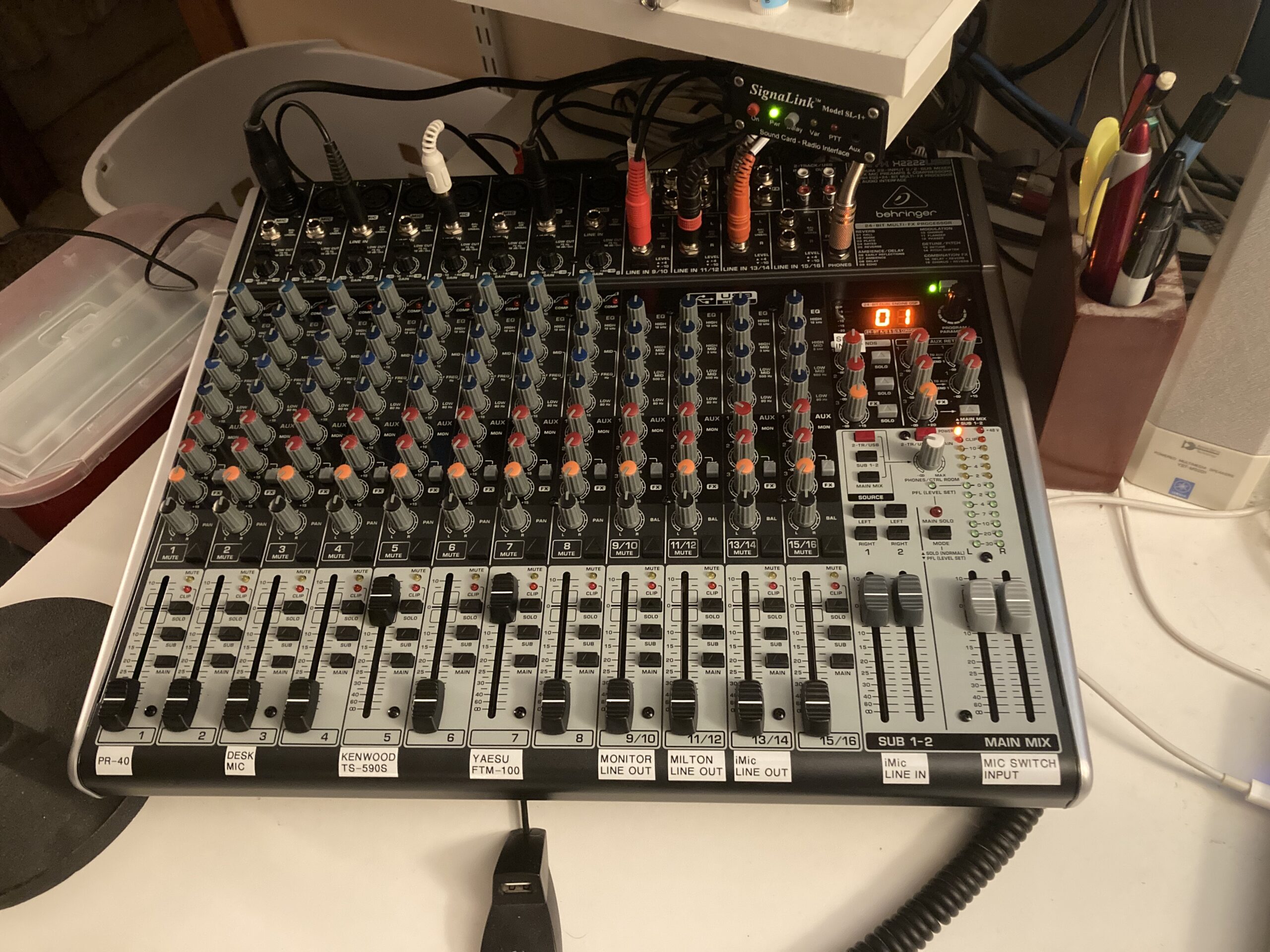
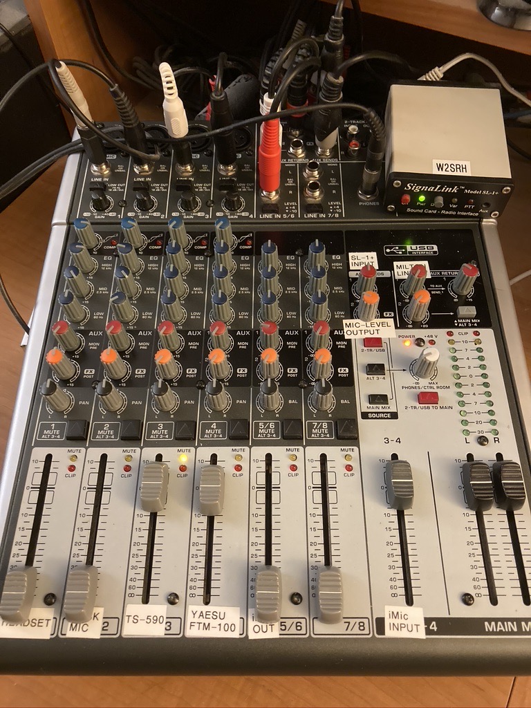
Finally, everything is where it belongs. As mentioned previously, I had received a mixer for Christmas but found a problem with it and swapped it for another. That one had a problem too, and then I got a different one completely. That one had a problem, and I realized those problems weren’t a problem at all if I did things a little differently, but then it had another problem. It was returned for another, and then I waited. And waited. And waited. After about a month I asked the vendor if they could tell me anything about availability, and they said they could not, but offered to change my gift card (which they created while waiting for the restocking) into a normal refund to my original payment method. I agreed with that and thanked them for their help, and then made the order with another vendor that had them in stock. And that one arrived last week. After work I unpacked everything and made quick work of getting things connected yet again – a bit easier of a task since I had everything noted down in Joplin for where things will go and all the appropriate settings – and after testing as I went I even made up the new labels for all the channels and got everything squared away. At last!
Last night after everyone went to bed, I started fiddling a little. One thing I was unsure of is the audio levels from the mixer into the mic input of the radios. I do have a roughly 40dB T-pad in line there that should be making the audio level decent, but I was afraid that it might be too hot now that I am connecting it differently. On the old mixer, I used the Aux Send 2 (post-fader) rail to feed the T-pad and my microphone switch input, which meant anything was mixed down to mono to head there. But on the first mixer I tried to put here, Aux Send 2 was now used as an input to the effects processor. I could still use it if I wanted to, but that meant if I wanted any effects I would have to choose which to use it for at the moment, and if I wanted any effects to go into the radio (no idea why I’d want to, but it’s a possible option) I wouldn’t be able to. So I thought, why not use the main mix output? Well, by default it’s stereo, so truthfully I should use something to mix that down to mono. But then again, what would possibly come out of all this that would be stereo? Well, the only thing that is likely to be stereo in the mixer at any time is music, and I won’t be playing music into the radios, so that’s not an issue. Anything else I can or should be able to mix down to mono as it comes in. So, I simply and arbitrarily chose the left channel to feed the pad and the radios.
The issue would then be, is the audio level OK? Audio checks are very subjective – you’re not only depending on your transmission, but the other person’s reception, and their perception of it all. I don’t like that kind of variability, I’d prefer something a little more … scientific. Or at least subject to my own opinion! So first I went to websdr.org to find a device somewhere that would hear my signal. Neat thing about websdr locations, you can usually record a short bit and have it sent to you, so not only can you hear what it sounds like live, you can play it back and compare it. So I found one that heard me, made a couple recordings at a couple different microphone gain levels, and downloaded them to my computer. Only… they sounded pretty much the same. I noticed, however, that the automatic level control (ALC) meter on the radio was bouncing quite a bit at one gain level, and didn’t move at all at the other. ALC is used when the audio signal going into the mixer in the radio is too high and needs to be attenuated a little so it doesn’t overdrive later stages. If you’re running digital modes, you don’t want that meter to move at all – if it is, you’re overdriving things and since those signals are steady you can and should turn the input to the radio down until the meter doesn’t move or else it might distort things. But for voice, you want it to be there a little bit, because it means you’re driving with enough power to fully load the radio’s later stages. Turn the audio down a little, and maybe some of your voice won’t be loud enough to fully drive power output; turn it up too high, and you’ll saturate things and start clipping and creating bad audio.
To solve this, I loaded a webpage that lets me generate a constant tone. 400Hz works fine for this purpose, and I sent it to a different output of the computer and therefore input to the mixer. I could then adjust it so that the level coming into the mixer would be just around 0dB, as “normal audio” should be going into it. Next, turn the radio’s power down as low as possible since I don’t need to really transmit anything over the air for this test (a dummy load would be better, but I don’t have one and would have to swap cables around to use it anyway – limiting test transmissions to as short as possible, and as low a power as possible, is also good practice). Finally, hit the button to adjust mic gain and key up the radio. Now as I adjust the setting, I can see what the ALC meter is doing, and since the audio going into it is steady it’s easy to tell if I’m on track with my adjustment or not. I set it so that it got a little less than 30% of deflection, meaning with a 0dB audio signal it would be just a little too high for the mixer stage in the radio and need to be attenuated a little. Now, turn off the audio tone and try it with voice, and huzzah! I could see the ALC moving while I talked, but didn’t see it hitting more than about 60% meaning there’s still room to attenuate if I get loud, but I’m fully driving the radio’s amplifier with the most audio I can. That’s a lot more scientific than “how’s my audio sound?”!
Last, I wanted to do something similar for the Yaesu VHF/UHF radio. Unfortunately it doesn’t have an ALC meter to look at, but I can very easily listen to its output. I pulled out an audio cable and adapter and plugged my handheld into the mixing board, then routed that audio to a different input on the computer. Fired up Audacity and told it to record on that input only when there’s a signal present, then turned the FTM-100 down to low power and made a few tests. Plain FM, low mic gain and normal mic gain. Then C4FM, normal and low. Listened back, and normal gain not only was louder and easier to hear, but it didn’t sound distorted at all. I probably should have tried high, and then tried it with the stock mic as well.. maybe that’ll be an experiment for another time.
So, everything is finally done. New mixer is in place and working extremely well – I’m happy to have real mute buttons, and two extra rails (one new and one newly opened up). I’m using three of the four stereo inputs already, but don’t really have a plan for the fourth yet though I’ve had an idea or two for the future. I’ve got four mono inputs available as well for things I might want to do. It’s every bit as versatile as the old setup, and quite a bit more. And let’s be honest… it looks freaking awesome.
It’s a UNIX system! I know this!
Old days, Good times I remember. Fun days, filled with simple pleasure.
–Chicago, “Old Days”
As mentioned last month, I picked up some kits to put together recently and had a blast doing so. I’ve already detailed the Altair 8800 kit that I assembled, so now it’s time to talk about the next one – the PDP-11/70 replica called a “PiDP-11“. It was every bit as much fun as the previous kit to assemble, though a bit more challenging!
[Note, in order to see captions on the photos, you’ll have to click through to the gallery on Google Photos]
This kit was shipped to me from Panama, so it had a bit different packaging in case it had to be opened by customs (mine wasn’t). Sorting through all the parts I found everything was in good order and re-read the instructions for assembly (much like the last kit, I’d already read through them quite a bit before things arrived). The only thing which is not part of the kit is a Raspberry Pi itself, and while I had one at home that I could use I wanted to be able to use wireless to talk to it; when I realized the wireless adapter would be about half the cost of a new Pi 4, I decided to just get the new Pi with the built-in abilities. The extra power wouldn’t hurt, even if it’s emulating an old machine!
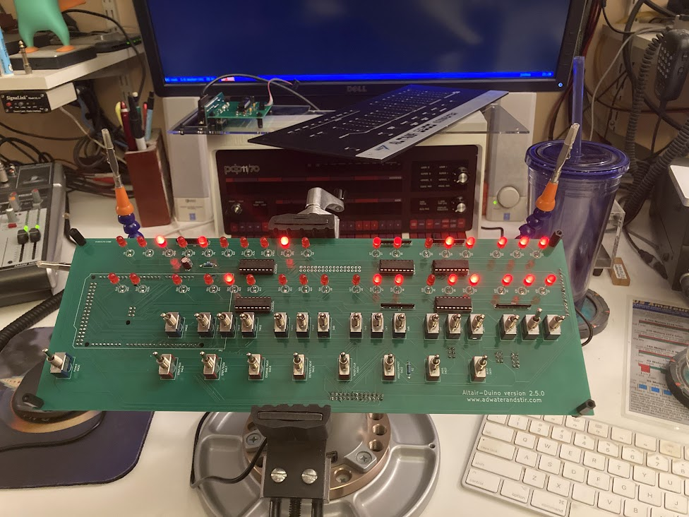
Since this time I wasn’t starting until after dinner, I knew I wasn’t going to have a lot of time to work on it before it would be time for bed, but I figured I’d get some of it done at least. I got as far as seating the LEDs into the board before I called it a night. By then I had all of the diodes and resistors installed as well as a couple other components, and had come to my first conclusion about this kit: the pads for all the components are extremely tiny. I use a fairly small soldering tip on my iron with a wedge shape that works well on through-hole work, but for this I really should have swapped to the pinpoint tip that I have for doing SMD work. Unfortunately I didn’t come to this conclusion early enough to make it a worthwhile change, because it would have taken too long to wait for the iron to cool off to swap tips the first night, and on the second night I was soldering things that were landed on larger pads anyway so it wasn’t a problem anymore (and in fact, I was going to be doing the switches the second night and definitely wanted the larger tip for those).
Testing the kit before the switches went into place was nice, and involved seating the Pi on the back panel. One nice thing is that it’s mentioned multiple times in the instructions that you need to put something to insulate the Pi from the back of the board to avoid shorting out any of the LEDs, however the socket has been redesigned to be extra tall now so when the Pi is seated on the back it sits high enough off the board that there’s no danger of shorting things unless you leave large tails on the components and don’t trim them. Since I don’t do that, everything was fine, and the test succeeded. Time to move on to the switches, which was definitely the hardest part of things. By the time I was finished, my fingers were in a bit of pain (not just from arthritis) and I found myself thinking, “this is good enough.” Now that’s not a way to say I was giving up on it, and things do look good, but maybe they aren’t aligned perfectly side-to-side or up-and-down. As a replica of a PDP-11/70, maybe it’s not exact in that sense, but I’m perfectly happy with it – there’s no part where I look at it and wish I’d done it better.
So how do those switches get installed differently than the Altair? Well with the Altair you set all the switches in place and then rest the front panel over top to line them all up. On this, however, there’s two stencils that come into play; one stencil goes just on top of the circuit board and the switches go through it, and it also contains the information on it for which direction each switch goes as well as the color and type (momentary vs. toggle), and the other template goes over top of the switches to hold them into place and keep their spacing up-and-down and side-to-side. Once everything is plugged in, you are supposed to “wiggle” the lower stencil up over the sides of the switches and then use some zip ties to hold the two stencils together which in theory keeps everything where it’s supposed to be. In practice, this was still an extremely difficult endeavor and left me wondering a few times if I was going to get it right or be horribly disappointed. In the end when I started soldering, I realized that I was chasing perfection at the expense of a good result, and I was going to either hurt myself or damage something if I continued at this rate. And you can see yourself in the photos linked above, some of the switches may be a little closer to each other than others, and some may be a little higher or lower than others, but nothing looks like it was slapped together without a care and assembled poorly. It may not meet the rigorous standards of DEC in the 1970s with a manufacturing plant at their disposal, but I think it’s perfect for me.
After a few more touches everything was done, and it was time to close up. I did leave the back panel off for a bit because I wanted a different power cord than the one I’d bought, and I installed an oversized grommet and a couple zip ties to create a strain relief as well. At some point I may want to install panel mount USB or Ethernet ports, but for now I’m perfectly fine using SSH over the wireless network, and I can use VNC to display the rPi’s console as well if I want to get more out of it or do other things. And now I have two retro computers with immense amounts of history to explore and learn more about since they were far enough before my time to have been gone when I became aware of the digital world. I’ve already started with a few things, running CP/M or 2.11 BSD, various flavors of BASIC, and of course entering in small programs via the front panel which is part of the whole purpose! Oh, and if you’re curious about the title of the post, the Digital Equipment Corporation PDP-11/70 is the machine that helped UNIX gain a foothold in the world, having been ported to it from the earlier PDP-8 where it started at Bell Labs. So aside from the blinkenlight factor, I really wanted a PDP because it’s kinda the reason why I do what I do in the end.
Look, Ma, No Wires!
Out in the woods, or in the city, it’s all the same to me.
–The Who, “Going Mobile”
When I’m driving free, the world’s my home, when I’m mobile.
I was about to type up the post about my next soldering project, but I decided I’ll jump a little out of order. I finished that one before I did what I’m writing about here, but this finishes up the Altair 8800 that I posted about earlier, so let’s wrap that one up first. As a friend of mine likes to say, “that makes sense. Let’s do it anyway!”
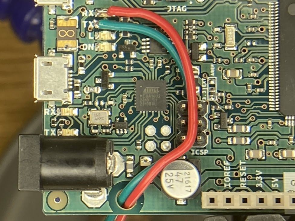
First things first, I looked at the Arduino and the tiniest soldering iron tip I had and thought, “hold my beer.” Yep, I was going to try to solder on top of the LEDs for the TX and RX lines and squeeze one more serial port out of this sucker. And ya know what? I did it. One line went on easily enough, and the second one I thought I had but it popped off when I moved the wire to route it nicely, so I tried it again and it stayed put that time. The wires themselves are breadboard jumpers I got for solderless breadboard work – I cut one end off and stripped a tiny bit of wire, then tinned them (and left a little extra solder on the end so it would be easier to affix it to the Arduino). I routed the wires through the ICSP header on the board and out through one of the mounting holes for strain relief, and everything went really smoothly. I just kept saying to myself, “Red for RX” so I knew which was which. These LEDs are normally usable by the Arduino through software, but not actually “attached” to any of the I/O pins on the headers, so if you want to use them for something other than a light show you have to do this. Who would be crazy enough to do it though? Well, someone who didn’t want to give up either the physical DE-9 serial connector on the back of the Altair, nor the VT100 emulator built-in and attached to a daughter card on the back. Now there’s four options for talking to the “console” of the Altair – USB directly to the Arduino, DE-9 serial, VT100 emulator via VGA and USB, or Wi-Fi!
I powered things up on my workbench, connected to the ESP-01S on my phone, gave it the right config for my wireless network, but couldn’t get any data from it. Alright, moved the whole thing over to the computer desk so I could plug the USB into the computer and talk to it that way. After a couple other false starts with things, I finally got comms to it and told it to load the profile that I thought would have the right information on it, and it said the file wasn’t there. It was at that point that I realized the configuration profile didn’t exist in the memory of the Arduino, but instead on the SD card that I use on this. The SD card that is still in the card reader. Which is on the daughter card. Which connects to the header on the right side in this photo (back of the board). Which is sitting on the workbench because I didn’t hook it up while I’m testing things here. <insert forehead slap sound> So after I manually told the software to use the other serial port, I verified that it was talking properly, then powered things off again to finish with the install and closing of everything.
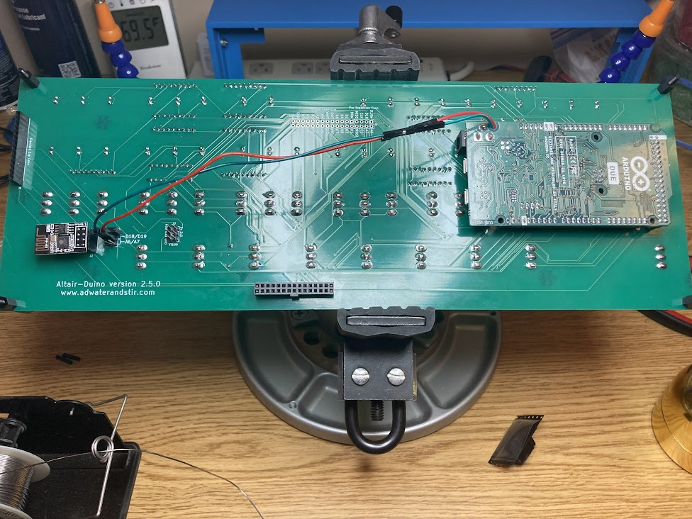
After the breadboard jumpers, I then had two female-female jumpers which worked as extension cables to bring the wiring over to the 6-pin header newly soldered to the board. Normally one would use jumpers on the left and right side to connect the center pin to one of the pin pairs to “steal” one of the other serial ports. By plugging the jumper wires to the center pins, I can connect right to the ESP-01S without soldering to it directly. I left the two jumpers hanging off the ends of the headers so they’re stored with the system but not in use. After this it was time to button things up, and really it all looks the same as the original post at that point since this is all internal. I did notice that the daughter card (specifically the VT100 emulator) seemed to push down on the ESP-01S a little, but there’s no shorts involved (the part pressing on it is the top of jumpers, which aren’t open on the back) and it doesn’t seem to be a huge issue. Definitely a tight fit though. Along with the ESP-01S, I also got the missing nylon bolts to finish mounting things properly (the front panel was otherwise only held on with half the screws it should be and two holes were left there) so everything is buttoned up nicely and looks phenomenal.
So now I’m even more happy with this item, because I can simply telnet to the IP address it gets assigned and automatically get a serial connection to the Altair. I’ve been playing with some other things on it too, but maybe I’ll write about them separately. So far I can say it’s been not only a huge source of enjoyment to build the kit, and even to look at it (let’s admit, it’s quite a pretty piece of equipment), but also to “toggle in” a program to load things – even if I don’t really have to with how the emulation works – and to start exploring some of the operating systems I’d only known about in passing. Plus… I’m almost ashamed to admit, I don’t think I’ve ever played Zork before. And I know I’ve never finished Adventure.
Comments
Join the conversation on Bluesky
-
2025/03/02
Hm, ok there’s one thing this new plugin doesn’t do as well – the image from the post didn’t come through too. Images are a Good Thing! Alright, I’ll have to think about things maybe, or use the other plugin to post things and this one to “pull” in comments. This calls for More Science!

Saturday in the Park
Can you dig it? (yes, I can)
–Chicago, “Saturday in the Park”
And I’ve been waiting such a long time
For today
I mentioned previously that I had ordered a couple kits to assemble, and the first one – the Altair-Duino – arrived and got finished a scant few hours later (because I was so looking forward to it, and I stayed up a little too late playing with it, because it’s so freaking awesome).
[Note, in order to see captions on the photos, you’ll have to click through to the gallery on Google Photos; you’re not missing a hell of a lot this time though.]
The kit arrived Saturday early afternoon, and I set about earnestly unpacking it and checking things out. My youngest was in the process of finishing his own soldering project on my workbench so I knew I couldn’t start right away, which was fine – I’d need a bit of time to sort through all the parts anyway and make sure everything was there, and he’d been looking forward to his soldering project for a while and had started it Friday night after dinner. Everything was packed very well, and when pulling the parts from the box my first impression was the weight and quality of the metal frame for the unit, as well as the details on the front panel piece. The back panel is mostly clear acrylic with a small bit of black acrylic where the daughter card and VT100 emulator attach (more on that later). Overall I was already pleased with the kit.
After dinner and having sorted all the pieces, I look at what was before me. The parts list said I needed a 220k? resistor, but I had a 220? resistor. Reading forward in the instructions, and looking at the board, I found the ‘k’ was a typo in the parts list so I was good there. But it also said I should have 8 of the nylon bolts, and I only had four. Reading ahead, I wasn’t sure if I really needed all 8 – there was at least one spot where I saw they were used and then later removed. Either way, that wouldn’t be until the end stages of assembly so I figured I could forge ahead and worry about them later. Everything else checked out, so I started putting components to circuit board and it wasn’t very long at all before I had to warm up the iron.
Everything went on very easily. There was hints like putting the switches in place and then laying the front panel over them before soldering so that when you do they’re lined up side-to-side in a way to fit through the holes easily so you’re not surprised when it comes to final assembly, and another trick of installing all the LEDs into the holes, mounting the front panel, and flipping the whole thing over on its face with a satisfying “clack” while they all fall forward into their respective holes. A slight tap on one or two to get them to line up as well, and then you can solder every one in place – and all of them will be at the perfect height and angle to fit correctly on the front. Of course in the end when I was muscling things into place I ended up bending one of them the wrong way, but I was able to get it back pretty easily and everything looked fine in the end.
A few comments about the device itself. The brain of the whole operation is an Arduino Due which is preprogrammed with the software, which is easily reflashed if there’s a software update or you completely hose things and need to start over. There’s also an SD card with a bunch more software installed on it that can be loaded. The programming port is routed to the back panel with an extension panel-mount cable so you can always get to it easily for programming or powering it up, and the default serial connection from the Altair is routed to that connection as well. There are other options too, including one serial port that is also presented on the back panel, and another which connects to another card mounted on the back which contains a VT100 emulator running in a PIC microcontroller with a VGA port for display output and a USB port to connect a keyboard. I found I didn’t have the right cable to try connecting my VT320 to the serial port (I used to use it connected to my computer to receive syslogs, so the custom cable I have for it is a null modem), and I haven’t dug an old monitor out with a VGA port on it to try the VT100 emulator. Maybe I’ll do that in the next day or so, but then again the next project will be here on Tuesday so it might wait until after that.
What can be done with it? Well, it’s a clone of an Altair 8800, so anything you can do with that, you can do with this. I used the panel switches to enter in a couple programs and saw them work, and could demonstrate binary math and how assembly language works, how to debug a program by stepping through the code to look at the instructions entered, how to step through execution one step at a time to see how it works, etc. I even adjusted the internal settings so the emulated serial port would “act” more like a real serial port and spit out data to the terminal at a whopping 110 baud as it should be. Then I toggled in a bootloader, executed it, simulated loading a paper tape drive with 4k BASIC and hit play. Sure enough it took around 17 seconds for the first stage to load, then another 6.5 minutes while the second stage pulled in the data, finally outputting a satisfying “MEMORY SIZE?” to the terminal. I’m looking forward to exploring more about some of the operating systems that came and went before I got into computing, since my first foray into computing was an IBM PCjr with cartridge BASIC and PC DOS 2.10, right around when CP/M was making its exit.
Overall I’m extremely pleased with my choice. The kit is well designed and the manufactured parts done with precision, the instructions were easy to follow and the end result is a joy to play with and look at – so far everyone has commented that it’s one of the coolest looking things in the shack, and that’s while looking at an HF radio too. My only regret is that I didn’t buy the ESP-01S module that would provide for getting the device on my local network so I can just telnet into it; since I needed the nylon bolts that were missing from my kit, I asked if he could provide them with the module if I ordered it and he said yes, so that’s all on the way. I’ll have to decide if I want to commit to not using the standard serial port, or go through the process of soldering onto the TX/RX LEDs on the Arduino to basically squeeze one more serial port out of the device and have access to all three. I mean, I got it for hacking, why not hack right?
Part of me wants to make a video of using it or something, but I don’t feel like digging out a good camera to record it, or edit (because I’m a bit of a stickler for things being Just Right when it comes to that kind of production). Maybe the mood will strike me later.
Edit 2025/03/02: There’s three more photos at the end of the gallery from a follow-up addition which I cover in another post. Didn’t make sense to make a new album just for that.
Could Be, Who Knows?
Could it be? Yes, it could.
–Stephen Sondheim, “Something’s Coming”
Somethin’s comin’, somethin’ good, if I can wait.
[Personally I prefer the version by Yes, but that’s just me]
I’ve been wanting to get a project or two I can solder and tinker with, because I’m getting that itch. I’d keep looking at things like various radio kits, but the biggest problem with kit radios is that they tend to be directed at CW operators which I am not – even the most powerful kit radio I could easily grab ahold of would do max 10W SSB, and that’s not enough to make meaningful contacts for me. So while it would be fun to assemble and test, I probably wouldn’t use it much after that. And recently I realized that I’d been saving up some money but without a goal to save for. That can be a dangerous combination, so I went looking for something that would scratch that itch to build and tinker again.
Enter some retro computing items. Some years ago when looking to populate my wish list with more items, I stumbled across some things that I didn’t know existed. Of course there’s old computing stuff out there, and I love playing with it, but some of it is too old to be reliably dealt with – too hard to source the parts, or too expensive, too big, all kinds of reasons it’s not a Good Idea. Well, some enterprising folks out there have come up with good ways to handle that via emulation and replicas, and I am here for it. The first one on the list is a replica of the IMSAI 8080, which many will know as the computer that David Lightman uses in the movie WarGames.
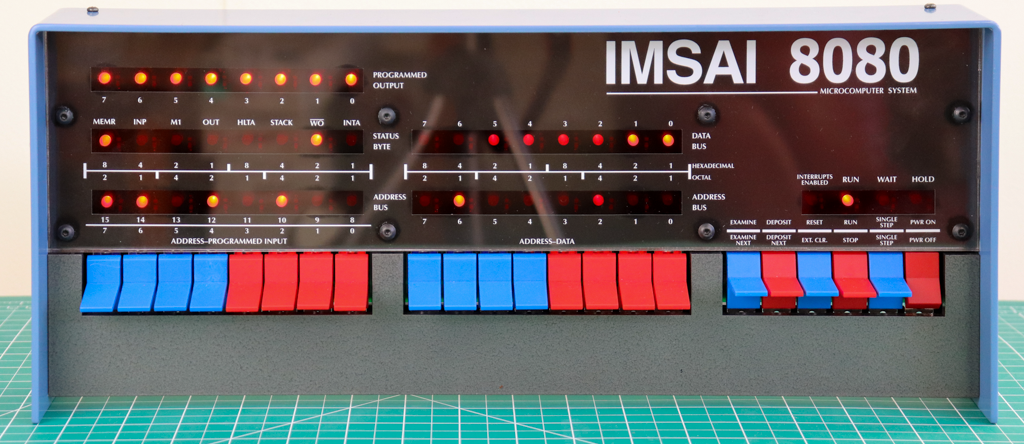
This replica is done by The High Nibble (love that name) and is available on his website. One of the main reasons I want one of these is of course the movie factor, but also because I love tinkering with old hardware, and why not? It has blinkenlights. That makes it better. One downside to this particular kit though is that it’s not readily available from what I can tell – the order form is more of an interest form, and after you submit your address you’ll get an email when a kit is available to purchase. It’s also a little more expensive than other items on my list, which is not a mark against this kit at all – I think it’s worth every penny, I just didn’t want to spend that many of them on one item at this time. So this one will stay on my list for another day, hopefully soon.
What’s next? Well, the IMSAI was one of the first “computer clones” (those who remember the early 90s to 2000s may recall when things went from “IBM or Apple” to “Send In The Clones” as everyone started making mostly compatible hardware). The original that it copied was the Altair 8800, and I remember seeing them as well when I was first getting into computing. You may have too, as it’s a pretty iconic look.
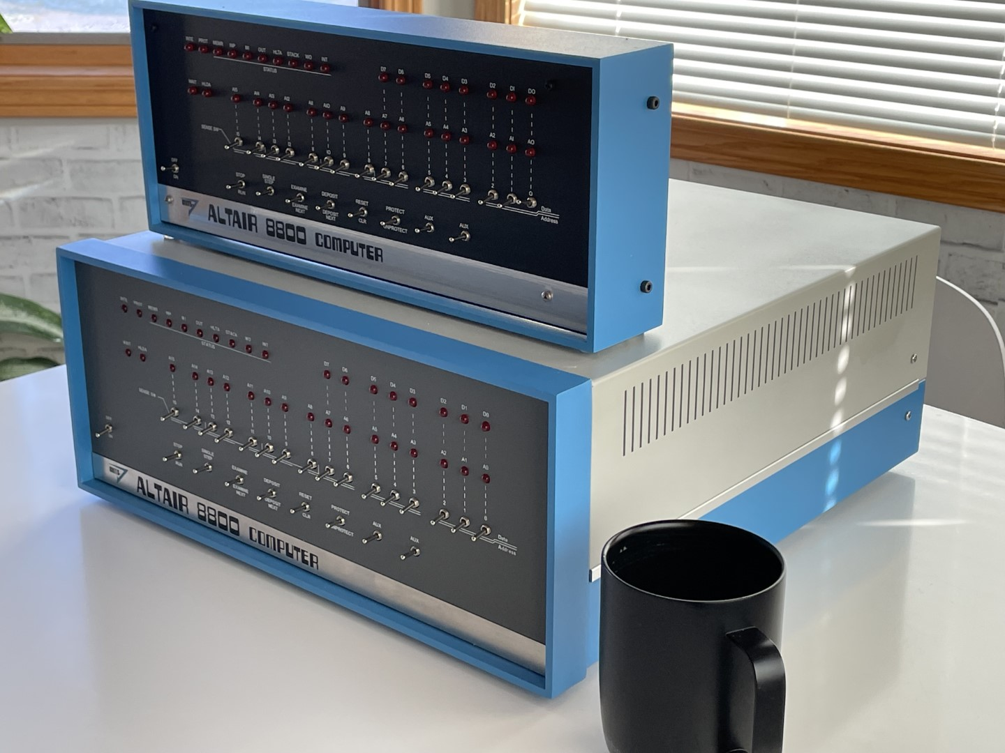
Adwater & Stir (another awesome name) offers the Altair-Duino which comes in two flavors. One is pretty close to the original in terms of space and expandability, and the other is slightly smaller and much more shelf friendly (and cheaper). Since I’m more interested in tinkering and building, and don’t plan to add expansion cards at the moment (nor do I care to have it take up a lot of space on a desk or cart somewhere), the smaller “experimenter” fits the bill quite nicely. It keeps the cool factor between the blinkenlights and the panel switches, where you can actually “toggle in” an entire program if desired but not necessary since a bunch of stuff is preloaded on the Arduino inside for you to cheat and load very quickly. But if you want to bit bang on the panel, go for it – and that’s exactly the kind of thing I like to read about. Reading those pages, I also saw a comment at the bottom of one of them that gave me a head scratch (or maybe a record scratch):
I also have to say “thank you” to Oscar Vermeulen of Obsolescence Guaranteed for his recreation of the PDP-8, which got me on this quest to recreate historic computers.
PDP-8 I thought? I don’t know much about the DEC machines, but they had blinkenlights too.. and I remember seeing them in the background of various podcasts where Steve Gibson was a guest (such as “Security Now”). So I moused over to there, and found something I could really get behind: the PiDP-11/70
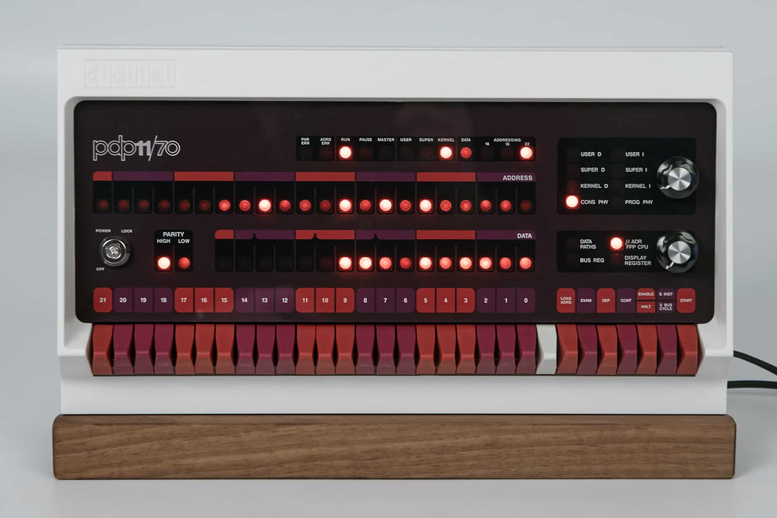
The PDP-11/70 was a computer from Digital Equipment Corporation and was instrumental in the design and creation of Unix. It’s also one of the last machines to still have a proper front panel with lights showing address and data information (later PDP-11s had their panels replaced with blank panels since after the boot sequence the switches and registers were typically not needed). As you may guess from the name, the brain of this one is a Raspberry Pi running the ‘simh’ emulation package, so while there’s the faithful recreation of the panel and operation there’s a lot more power internally to do other things, including running a full Unix if you so desire (nevermind the fact that the Pi itself runs Linux anyway).
So armed with all of this, what to do? Well, I counted up the savings I had sitting here and realized a bit of good news – I had enough for the PiDP-11 and the Altair-Duino. So I did what any self-respecting geek would do and ordered them both. Plus a new Raspberry Pi 4B since the only one I had sitting here is a 2B which, while it’s plenty powerful enough to run the emulator, doesn’t have built-in wi-fi (and the cost of a dongle is a portion of the cost of a whole Pi at that point). The Altair and the Pi will be here Saturday, and I hope early enough that I can get a good start working on it, while the PDP will arrive next Tuesday and probably have to wait until evenings and/or the weekend for its time to shine. I’ll be taking photos during the process to document it and share here, because.. well, this is just too freaking cool not to share. Oh, and if you’re curious about the term “blinkenlights”, it comes from a long line of posters and such that would be placed around machinery as a WWII-era joke. See an example below, or read the entry from The New Hacker’s Dictionary that explains it well.

Quiet, Please
Hush, hush, keep it down now
–‘Til Tuesday, “Voices Carry”
After two failed attempts at making my headphone attenuator, I finally got a working one. I showed an “in progress” shot in an earlier post, but mentioned that it didn’t work when I tried to solder everything together. Physics really, I wasn’t thinking ahead to having to slide the protective cover or shell over the whole thing and resistors don’t bend in the middle. I only really have one in-progress shot of the working one:
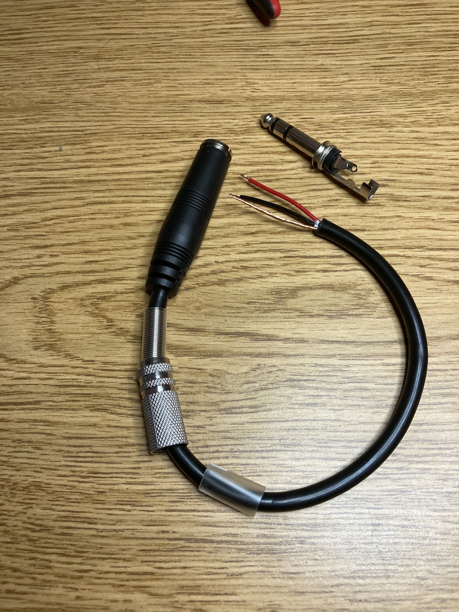
But the finished product looks pretty good if I say so myself:
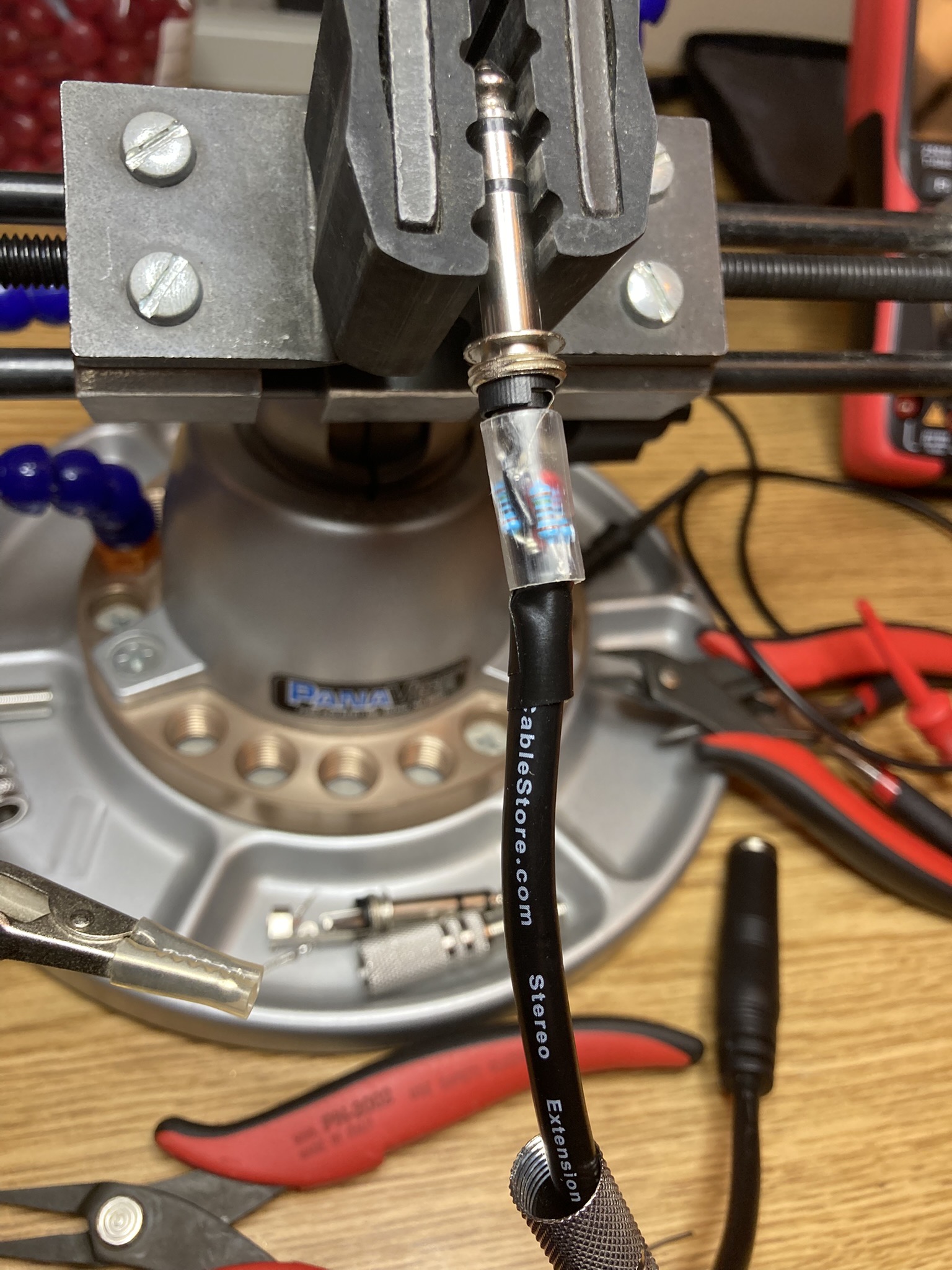
The biggest part of the problem is getting those four resistors in there correctly. I had done it with the “in-line” version but .. well, I didn’t like it anyway, so when it didn’t work I wasn’t heartbroken. This one works, doesn’t have shorts or wiggly bits that cause issues, and plugging my headphones into it and the cable into the board means I have a larger dynamic range on the one potentiometer as expected, and “loud” in the headphones can be made to be “loud” in the room so there’s no surprise (or booming headphones sitting on a desk somewhere).
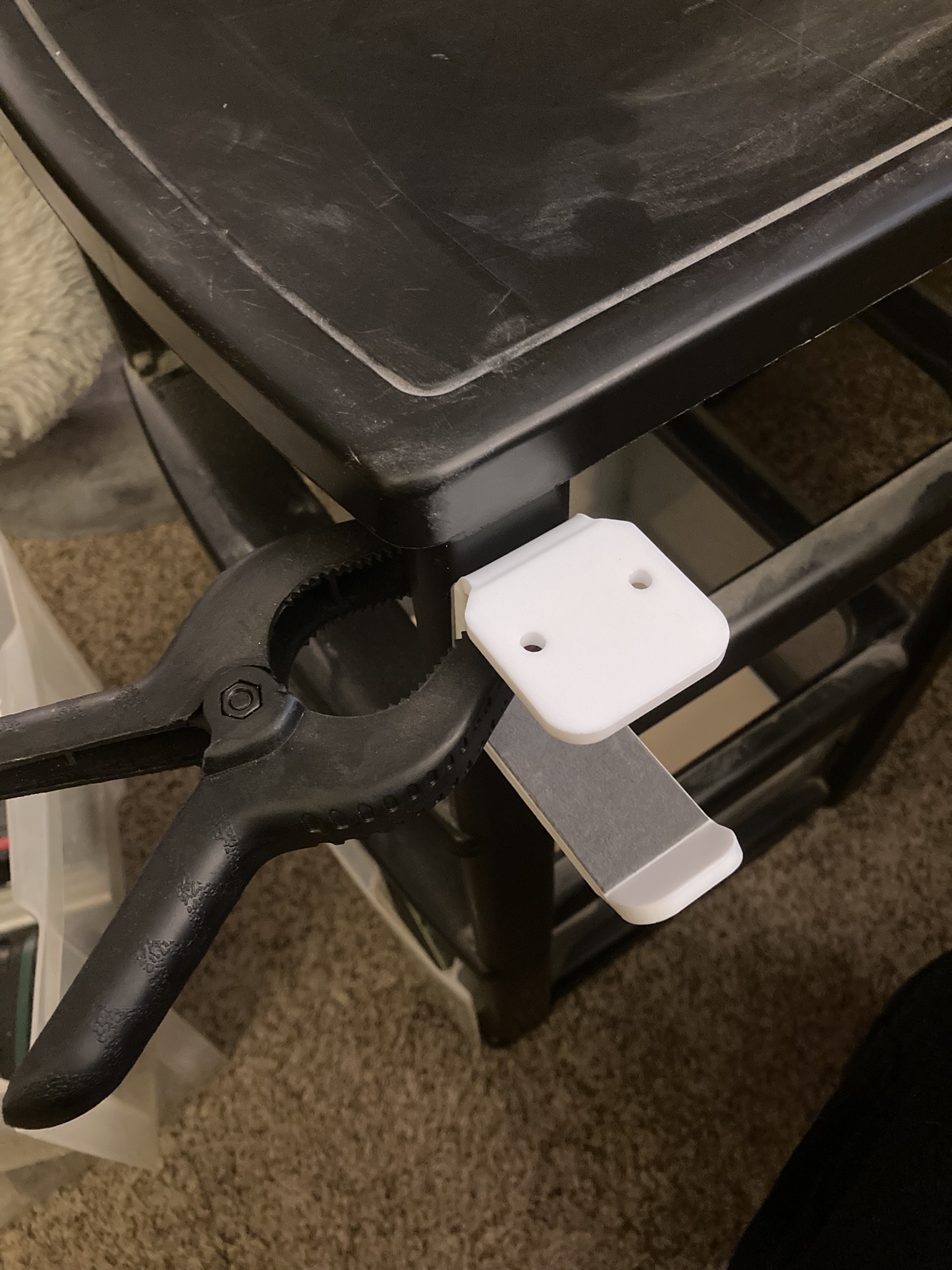
Speaking of headphones on a desk, I fixed that too. Or I will have, once I’ve given the adhesive some time to bond. This drawer is usually under my desk by my left knee, so the headphones will be nearby but out of the way, not taking up desk space, and also perhaps not getting dusty when they’re not in use. I could’ve screwed it to the underside of the desk, and still reserve the right to do so, but if this works then it’s less “permanent” and still useful, and if it falls off after two weeks I get a screwdriver and make it so.
All Mixed Up
You’ve got to trust your instinct
–311, “All Mixed Up”
And let go of regret
I seem to have had a run of bad luck with mixers lately. Why do I even have one? Well, I play with audio a lot, either because of various Zoom meetings, or because I do amateur radio stuff, or because I listen to music, whatever. And while the “simplest” solution for some of these is just to plug stuff right into the computer and have it work, I like flexibility. So my audio routing is… complicated. And I like it that way. Interestingly I’ve tried to write up how all that is done a couple times, and got as far as a few Reddit comments where I described it and a draft on here, but never officially published it. I don’t think this’ll cover the uses I wanted to with that post, though it will probably serve as a jump point, because the main issue here is that I’m annoyed with having to send back three mixing boards in less than a month.
Continue readingFixing a Hole
I’m fixing a hole where the rain gets in
–The Beatles, “Fixing a Hole”
And stops my mind from wandering
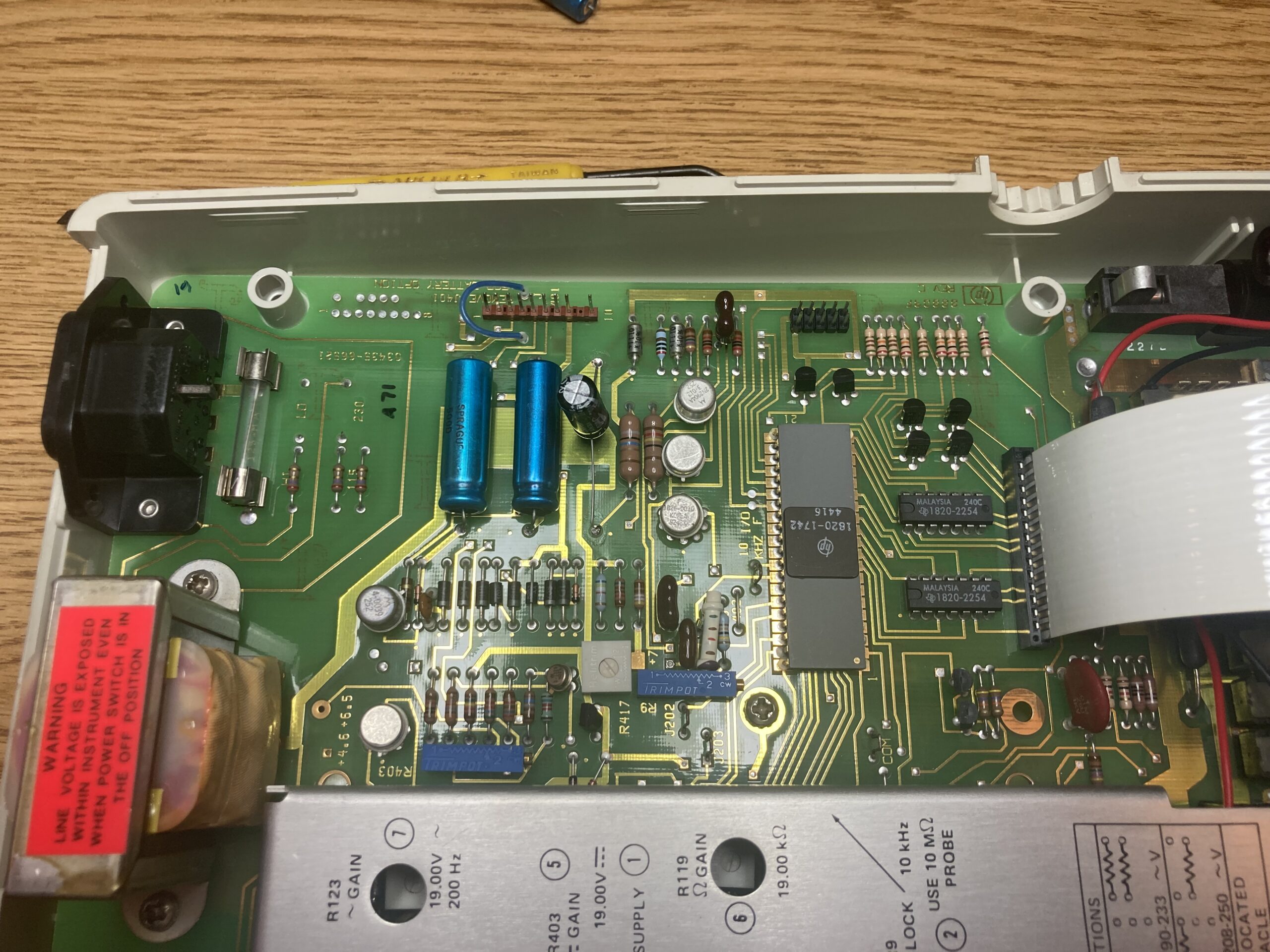
For a while I’ve had an old HP 3435A desktop digital multimeter. Picked it up at a surplus place for $60 so I could have a meter that sits on a shelf and is always ready, doesn’t need batteries, has a decent readout, autoranging, basically a bunch of features that my existing meters did not have. Recently when I went to use it, I found that the voltage it was showing was impossibly wrong – I seem to recall it was an AA battery I’d just removed from something marginally working but it read 0.2V – and then shortly after the only thing it would display is “OL”, its code for out of range. Around the same time as that, I saw a video from Great Scott! that talked about a portable DMM that also has a two-channel 50MHz oscilloscope. Now I already have an old analog scope here, but .. well, it’s old, and it doesn’t have a lot of the nice features that newer scopes do. So after getting that new meter in my hands, I decided recently to take the old one apart and see if I could find out what was wrong with it.
Continue reading
Comments
Join the conversation on Bluesky