
His eyes react to light, the dials detect it
–The Who, “Go To The Mirror!”
Well, I finally got something off my to-do list.
Many years ago, I set up this computer. It’s… hm. Alright, maybe that’s not where I should start. No, I should probably go back from the start now, otherwise I’m going to have to do this in like a flashback thing, and those get messy. Ok, I’ll try again.
There’s a lot of things one can do in amateur radio, and I enjoy quite a few different aspects of the hobby. Of course there’s talking to people, there’s tinkering with electronics, but you may not know that some advances in technology came about because of hams experimenting with things to see how they’d work. One such thing that hams took from the commercial realm and started toying with is called AX.25, which is “a data link layer protocol” used in packet radio. Without going into all the details, it means that hams can use their radios with fairly simple devices attached – like the kind we used to use to call up our Internet provider and get online, remember that one guys? Guys? Fuck we’re old…
Anyway, with a simple modem – in this case called a TNC or Terminal Node Controller – you can send and receive packets of data over the air. This created packet BBSs… hey remember those too? Ugh, nevermind. Well packet traffic is good for getting data from one point to another, especially if you have other stations on the same frequency that can bounce your signal further along than you can on your own, but there’s limitations to things. Again, I’m glossing over a lot of this because it’s not really important to what I did today, and I can already feel this is longer than it should be 😀
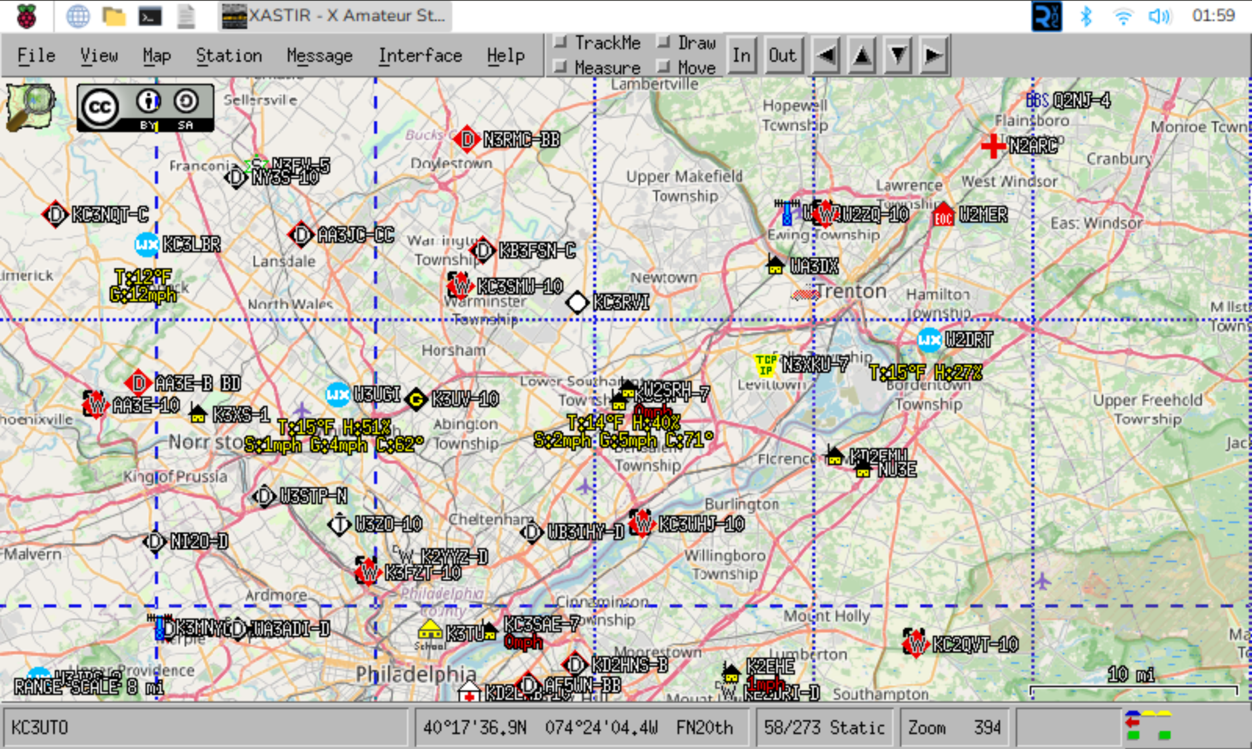
Back in the 1980s, Bob Bruninga – a research engineer at the US Naval Academy – came up with a way to track things using packets like this, and it evolved a few times until the 1990s when he started to test it with some amateur stuff as well. Eventually calling it APRS (originally the Automatic Position Reporting System, later with Packet replacing Position since it was meant to be more than just position reports) it was designed to use AX.25 packets in an “unconnected” way. No station was actually talking to another station directly, they just kinda “said” what they had to, and other stations that heard could do something with that or ignore it. Mostly, those packets had things like a position report (or GPS coordinates) but could also carry other information such as weather or short messages. But the packet also contained other bits of information about how “far” the transmitter would like their data to travel, and other stations might take the original packet and repeat it, changing it slightly, for example if it was a station that was high on a mountain with larger coverage. This is called “digipeating” (for digitally repeating) and digipeaters are a big part of the APRS network. With them, a user with a small handheld radio, or even a portable tracker, has a better chance of their signal getting heard by other stations. In the image above, you can see a bunch of stations positions marked on the map, and if one of them had been moving you’d even see a “trail” from it showing the path it took.
Later, stations were set up in an Internet linked manner and called “Igates”. The purpose of an Igate is to take the traffic heard on the radio and put it onto the Internet where it could be “heard” anywhere around the world by anyone interested. This allows for a more robust backend in some cases, where there might be good Internet service but spotty APRS coverage otherwise, so that the traffic generated in that area can still be seen elsewhere. Igates can be configured to also send some traffic from the Internet into the RF area, though that must of course be done with caution so as to not overwhelm the local area with junk traffic. Nobody needs to be hearing about your “special” weekly net when they’re too far away to actually hear it or join it anyway (and unfortunately APRS spammers exist).
Ok, I think that’s enough back story. And at this point I’ve probably taken up more time than you were willing to give me, so I’ll be surprised if you keep reading. But maybe I’ve only piqued your interest and you’d like to hear more over a cup of coffee. Well, go pour one and I’ll keep typing. So years ago I had an APRS station running at our last house, and it worked pretty well, but the software was running on my computer. The problem with that is that once I got a radio in the truck that could also do APRS, there was no way for Stephanie to use the software to send me a message or even look to see where I am (without looking on the website, of course). Plus it meant if I had to do something on the computer that took it offline, the APRS station went offline too. With Raspberry Pi machines being only about $35, and accessories not too much more at the time, I picked up a 7″ touchscreen display that the rPi 3B+ would mount right onto and configured them to run Raspbian Linux, installed my favorite APRS client Xastir on there, and now had the benefit that if my wife (and later my daughter) wanted to see what was up they could just touch the screen to wake it, and even use the nearby Bluetooth keyboard to send a message to me in the truck. In Morrisville, the station wasn’t highly useful because there was plenty of other stuff nearby, but I enjoyed running it. Once I moved to Trevose, however, I found that there was a bit of a dead spot near my house (which is also near where Street Road, I-95, and the PA Turnpike meet). So here, the station hears a lot of daily commuters, and helps to get their traffic not only heard onto the Internet but even repeated locally which gets heard across a large area. Oh yeah, did I mention that my station’s packets are heard easily in Somerset, Gloucester, and Ocean Counties in NJ as well as Northampton and Philadelphia Counties in PA? I’m in a really good spot here, and I love seeing that my station is able to help a lot of others.
But, I took it offline today, because I had to update the OS on it. I hadn’t in a long time, in part because I just wasn’t paying attention to it, and then when I finally did the OS was old enough that there wasn’t a clean upgrade path and a full reinstall was the best choice. I tried using a separate SD card – so if things went south I could put the old one back in – and it’s good that I did because things went south when I tried to copy data off the old card onto the new one and found it filled up. Decided to get a larger one, but that was sometime in August I believe, and the “Finish APRS upgrade” task was on my list since then. Well today, being I was home with three kids in various stages of flu-ness and not wanting to leave my safe area in the shack, I pulled the machine off the shelf and started working on it. Got sidetracked when the power supply I was using didn’t have quite enough oomph, and then again for dinner later on, but finally this evening I got everything setup and running again. And then after a shower I decided to write about it, which is why I’m finishing this up at 3am. But I got it done before the storm hit, which is nice. Oh, and not shown in that screen capture above, because if I left the NWS alert part on the whole screen would just be a red blob that says “ALERT” due to the impending snowfall. Which hasn’t started yet. Which also annoys me for various other reasons. Hopefully not as much as reading all of that just to hear “I upgraded my computer today” but.. well I thought it was interesting. Maybe you will too.

Comments
Join the conversation on Bluesky