But You Can’t Tune A Fish

I’m singing this note ’cause it fits in well with the chords I’m playing
I can’t pretend there’s any meaning hidden in the things I’m saying

–The Who, “Getting In Tune”

A long long time ago.. back when I wrote here a little more regularly, or at least tried to, I talked about some problems I was having with the tuner for my HF station. The first part of that story was posted here. Well, technically I guess the first part is this post, but that took place the day after the other one because I don’t always think linearly. Anyway, after all of that ended – which was some time later – I wrote a draft to just put a bow on the whole thing, and around that time stepped away from posting entirely. I kept looking at the draft now and then when I’d login but didn’t write it up. When I recently revitalized things I wondered if I should delete these draft posts, and I did take some of them away, but this is one I figured I could still write up and be relevant. So let’s finally end this thing, shall we? At least I hope it’s ended, I haven’t been using my HF station for a while lately and with my occasional luck I won’t be surprised to find a new gremlin took residence somewhere.

The tuner left my house around the end of March 2021, and I got notification from MFJ that they had it. Some weeks went by and there was no word, so I reached out to ask for a status update. They got back to me saying that apparently one guy was the one to work on them, and he had a backlog to get through and hadn’t got to mine yet. They promised an update, which I seem to recall they didn’t deliver on time, and I think I sent yet another follow-up asking for information only to receive a shipping notification that it was on the way back to me. I never did get any word on what was actually wrong, just a couple hand-scrawled notes about replaced components that didn’t make a lot of sense to me, but the tuner was back in my hands three months later. I remounted it and it seemed to be working better, but not for long. Strange problems like the SWR would bounce between infinite and 1:1 while tuning, on almost a regular period like something was swaying in and out of the way. Whatever it was, I wasn’t happy – I’d spent three months waiting for this to be fixed, was told it was fixed, and it was most certainly Not Fixed.

I’d been hanging out in IRC with a group of hams, and a smaller group of them who are somewhat local to me, and come October I grumbled about my antenna problems in there. Three of the folks in channel – Andrew (KC2G), Chris (K2CR), and Jeremy (AC1LQ) – started walking me through some troubleshooting steps. I knew I was too “in the middle” of it and greatly appreciated an outside look, so I took their advice and reconnected the old unun transformer that I originally bought with the antenna. Back then, I used an antenna tuner inside the house, plus with a specific length of coax the whole system worked well and I was able to operate 160-6m. But trying to do that here wasn’t working as well, at least in part because I didn’t have the same length of coax between the tuner and the antenna anymore (which would change what point a standing wave node would be, and makes the tuner easier able to adjust – though it doesn’t do anything for the signal coming in or going out). So I figured the solution was to get a tuner that is as close to the mismatch as possible – right at the antenna – and that might help things to work better. Only, it wasn’t working out so great after all.

Back to the present, I hooked the unun up as close to how it was back when I first setup the antenna. Then, the whole length of the antenna was “hot” and the ground only connected to the ground plane and wires run along the grass. When the new tuner kit installed, one step was to isolate the bottom most antenna section and make that part of ground, and then everything from that above is hot. This shortens the antenna by one section, but supposedly is the better way to run it – I wonder if it’s because that’s also where the tuner mounts, and it keeps RF from being radiated right into the side of the tuner that way. Either way, the tuner is now seeing the entirety of the mismatched antenna right at its inputs. So by installing the unun and connecting that, then running through the tuner, now the unun will take up some of the mismatch before the tuner gets to it. Headed back into the shack to test things out, and .. eureka! The tuner was working much better, on all bands except 160m (to this day I still have no good way to tune up there, though I have ideas I just haven’t got around to trying to build something for it).

I made one more trip outside to reset the tuner’s memories completely, since I’d now mucked with the whole antenna system to the point that any learned tunings for a frequency would have to be relearned. To do that you have to open the case and have power applied while holding down certain buttons inside the case – the tuner is basically the same as the desktop model but without a meter or display of any kind, but the button switches still exist on the circuit board. Anyway, while I have it open and am looking at it, I found something else too:

Close up image inside my antenna tuner showing a complete lack of solder on the wire connecting the ground lug to the circuit board.

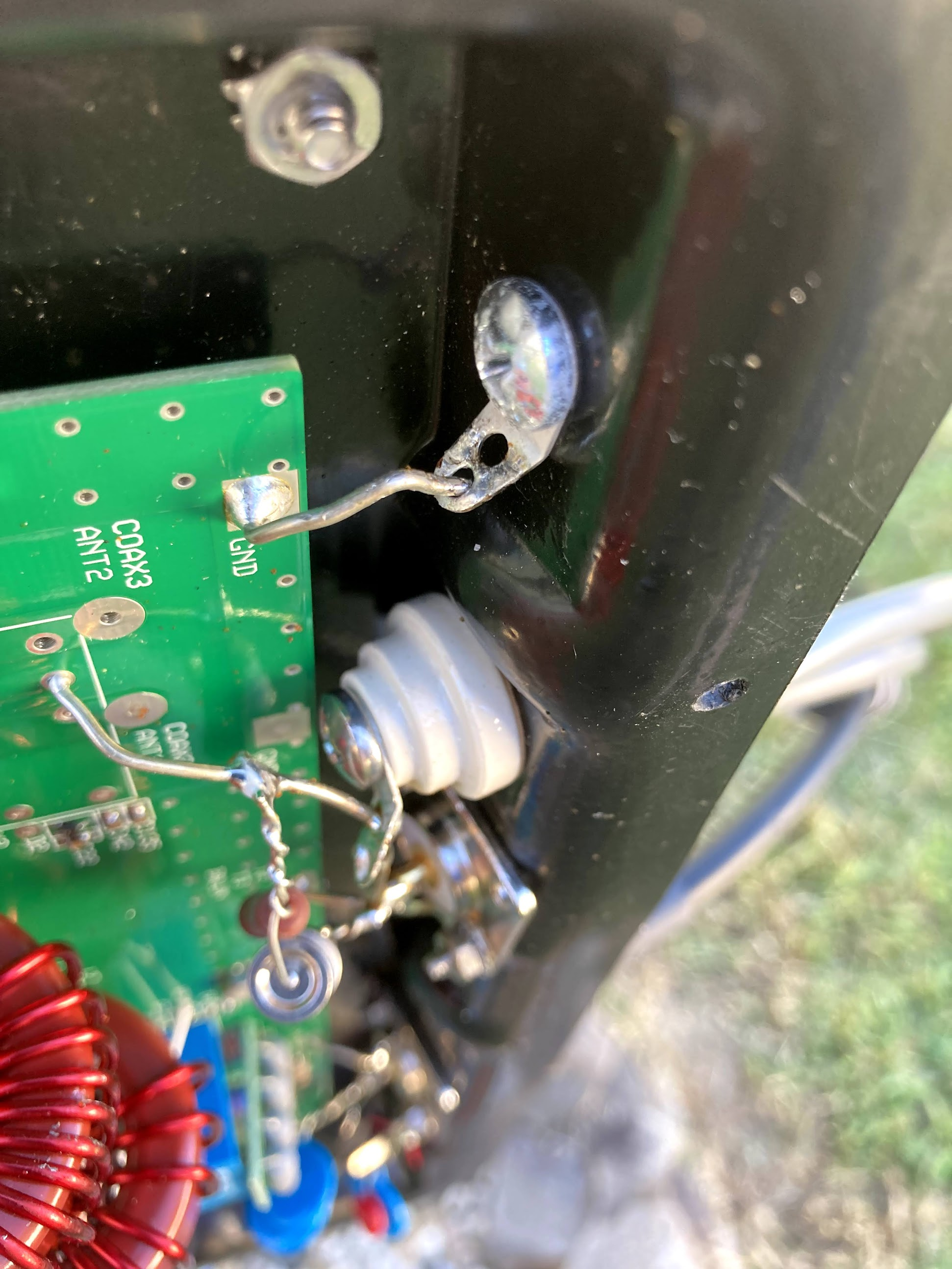
Turns out when it came back to me, the ground lug that connects to the ground for the antenna was never soldered. It’s just barely touching there, and probably making sporadic contact (and arcing I’ll bet too). Not an issue now that I’m using the coax connector to talk to the antenna, but when it was connected through that lug, I definitely wasn’t getting a good ground. Pretty good chance that was around 90% of the problems that I had when I set things back up, and of course I didn’t catch it because why would I open the tuner and look inside when I got it back from being repaired? Ugh.

Now I just need to get on the radio more often and make all this worth it. As mentioned, this all happened in 2021, and by the time it was all wrapped up I had just started to fall out of radio again. Made some contacts in February ’22, and again in October ’22, then a smattering in ’23 and ’24 but nothing much. Maybe with the recently upgraded audio board, cleaned off workbench, and a little rearranging of things in the shack, I’ll get back on the air again.

Posted in Ham /

Basking in the Green Glow

Love will find a way, if you want it to

–Yes, “Love Will Find a Way”

This makes me almost inordinately happy. Yes that’s an IBM Model M “clicky” keyboard. PS/2 output on it connects to a PS/2 -> USB adapter plugged into the Altair’s VT100 emulator port, and a VGA monitor displaying the nice green glow of a terminal. I wasn’t thinking I needed to do it, but now I feel like I really do need to get the VT320 hooked up and working on this – even if it’s deeper than this LCD monitor, it’s smaller and would fit better somewhere. I don’t know where that would be, because I wasn’t planning on having a display next to this normally, but… love will find a way.

You Are In A Maze of Twisty Little Passages, All Alike

He spoke of lands not far, nor lands they were in his mind

–Yes, “Wonderous Stories”
Image from the Atari 8-bit game "Jewels of Darkness" showing a half screen drawing and the opening text of the game.

As I’ve been getting into more retro computing (see thing one and thing two), there’s some things that a lot of people ask when I mention the new equipment. One of the first was “does it run ZORK?” While the answer is yes, Zork isn’t a game I ever really played – just kinda knew about it. Again, it predates my start in computers a little, and while it did still exist in other forms I didn’t hear about it until much later when the shine wasn’t as bright for me. But there was a game that I played a lot of, and I found it was there. First, a little history.

When I was a kid, a friend of mine had an Atari 800XL 8-bit computer. We would play with it a lot when I came over to his place, and a couple times he brought it over to mine when we’d have a sleepover. Lots of games on there that I remember playing and enjoying. At one point, he was looking to part with it – he wanted money for something else and hadn’t been using it anyway – and I happily offered to help. The transaction completed and I became the proud owner of it and a wealth of accessories (tape drive, disk drive, large box of floppy disks, even a few cartridges). I still have it all today, and have shown it to the kids, but the video output leaves a bit to be desired anymore and so while we still play Atari things we do it with the Retropie system running the atari800 emulator.

Well one of the games in there I really enjoyed, even though I wasn’t very good at it. It was called “Jewels of Darkness” and contained three text-based adventures that had 8-bit graphics drawn on the top of the screen like a storybook. The first of the games in that group was called the Colossal Caves Adventure, and I’d heard about it a little bit even back then but didn’t know much overall. So flashing to recently as I’m looking at some of the history for the Altair and the PDP, and I see mentions about Adventure. I dug in a bit more to find that Adventure was written on a PDP and spread out in the early days of the ARPANET, and eventually found its way into many platforms and systems including personal computers. As I was reading about some of the versions, I saw a familiar name: Roberta Williams. I knew her name well, as the founder of Sierra Games and creator of King’s Quest, one of the first games I played when we were getting our first computer (an IBM PCjr, the system for which the first King’s Quest game was created). Turns out Roberta got into gaming in part because of Adventure, and in 2023 she wanted to share that with others. Enter “Colossal Cave“, a first person 3D game which takes all of the gameplay from the original game and wraps it around wonderful landscapes and room designs and brings it to a new light. Once I saw this – and that it was available on the PS5 – I wasted no time adding it to my cart and checking out.

I spent the day playing through, and remembering how far I’d got in previous runs as a young one. Not very far, it turns out, because I never made detailed maps (which is almost a requirement) and wouldn’t notice things in the description enough to know there was something I should do. But when the game auto-maps areas as you enter them, and you can physically look around to see what’s in the space and what you could interact with, it’s a whole different kind of experience. On my first playthrough, with only having to remind myself of a few things (where is that damned trident anyway) I only fell short of a perfect score because I opted for the instructions at the beginning, which deducts 5 points. But not only did I have an immense amount of fun playing, I know at least one of the kids is interested in playing as well because it’s a puzzle type game that he can intuit from clues around what to do – like Hello Neighbor without absolutely needing to go find a walkthrough on IGN because there’s a valve handle hidden under the third potted rose, which there’s no way you could have ever known without looking it up.

Looking forward to starting Adventure up on the PDP soon and playing it as the original text game. Maybe I’ll even fire up Jewels of Darkness again and see what some of those half-screen images look like since I know I didn’t get to the end before. Then I guess I’d better start on Zork…

It’s a UNIX system! I know this!

Old days, Good times I remember. Fun days, filled with simple pleasure.

–Chicago, “Old Days”

As mentioned last month, I picked up some kits to put together recently and had a blast doing so. I’ve already detailed the Altair 8800 kit that I assembled, so now it’s time to talk about the next one – the PDP-11/70 replica called a “PiDP-11“. It was every bit as much fun as the previous kit to assemble, though a bit more challenging!

[Note, in order to see captions on the photos, you’ll have to click through to the gallery on Google Photos]

This kit was shipped to me from Panama, so it had a bit different packaging in case it had to be opened by customs (mine wasn’t). Sorting through all the parts I found everything was in good order and re-read the instructions for assembly (much like the last kit, I’d already read through them quite a bit before things arrived). The only thing which is not part of the kit is a Raspberry Pi itself, and while I had one at home that I could use I wanted to be able to use wireless to talk to it; when I realized the wireless adapter would be about half the cost of a new Pi 4, I decided to just get the new Pi with the built-in abilities. The extra power wouldn’t hurt, even if it’s emulating an old machine!

Since this time I wasn’t starting until after dinner, I knew I wasn’t going to have a lot of time to work on it before it would be time for bed, but I figured I’d get some of it done at least. I got as far as seating the LEDs into the board before I called it a night. By then I had all of the diodes and resistors installed as well as a couple other components, and had come to my first conclusion about this kit: the pads for all the components are extremely tiny. I use a fairly small soldering tip on my iron with a wedge shape that works well on through-hole work, but for this I really should have swapped to the pinpoint tip that I have for doing SMD work. Unfortunately I didn’t come to this conclusion early enough to make it a worthwhile change, because it would have taken too long to wait for the iron to cool off to swap tips the first night, and on the second night I was soldering things that were landed on larger pads anyway so it wasn’t a problem anymore (and in fact, I was going to be doing the switches the second night and definitely wanted the larger tip for those).

Testing the kit before the switches went into place was nice, and involved seating the Pi on the back panel. One nice thing is that it’s mentioned multiple times in the instructions that you need to put something to insulate the Pi from the back of the board to avoid shorting out any of the LEDs, however the socket has been redesigned to be extra tall now so when the Pi is seated on the back it sits high enough off the board that there’s no danger of shorting things unless you leave large tails on the components and don’t trim them. Since I don’t do that, everything was fine, and the test succeeded. Time to move on to the switches, which was definitely the hardest part of things. By the time I was finished, my fingers were in a bit of pain (not just from arthritis) and I found myself thinking, “this is good enough.” Now that’s not a way to say I was giving up on it, and things do look good, but maybe they aren’t aligned perfectly side-to-side or up-and-down. As a replica of a PDP-11/70, maybe it’s not exact in that sense, but I’m perfectly happy with it – there’s no part where I look at it and wish I’d done it better.

So how do those switches get installed differently than the Altair? Well with the Altair you set all the switches in place and then rest the front panel over top to line them all up. On this, however, there’s two stencils that come into play; one stencil goes just on top of the circuit board and the switches go through it, and it also contains the information on it for which direction each switch goes as well as the color and type (momentary vs. toggle), and the other template goes over top of the switches to hold them into place and keep their spacing up-and-down and side-to-side. Once everything is plugged in, you are supposed to “wiggle” the lower stencil up over the sides of the switches and then use some zip ties to hold the two stencils together which in theory keeps everything where it’s supposed to be. In practice, this was still an extremely difficult endeavor and left me wondering a few times if I was going to get it right or be horribly disappointed. In the end when I started soldering, I realized that I was chasing perfection at the expense of a good result, and I was going to either hurt myself or damage something if I continued at this rate. And you can see yourself in the photos linked above, some of the switches may be a little closer to each other than others, and some may be a little higher or lower than others, but nothing looks like it was slapped together without a care and assembled poorly. It may not meet the rigorous standards of DEC in the 1970s with a manufacturing plant at their disposal, but I think it’s perfect for me.

After a few more touches everything was done, and it was time to close up. I did leave the back panel off for a bit because I wanted a different power cord than the one I’d bought, and I installed an oversized grommet and a couple zip ties to create a strain relief as well. At some point I may want to install panel mount USB or Ethernet ports, but for now I’m perfectly fine using SSH over the wireless network, and I can use VNC to display the rPi’s console as well if I want to get more out of it or do other things. And now I have two retro computers with immense amounts of history to explore and learn more about since they were far enough before my time to have been gone when I became aware of the digital world. I’ve already started with a few things, running CP/M or 2.11 BSD, various flavors of BASIC, and of course entering in small programs via the front panel which is part of the whole purpose! Oh, and if you’re curious about the title of the post, the Digital Equipment Corporation PDP-11/70 is the machine that helped UNIX gain a foothold in the world, having been ported to it from the earlier PDP-8 where it started at Bell Labs. So aside from the blinkenlight factor, I really wanted a PDP because it’s kinda the reason why I do what I do in the end.

Look, Ma, No Wires!

Out in the woods, or in the city, it’s all the same to me.
When I’m driving free, the world’s my home, when I’m mobile.

–The Who, “Going Mobile”

I was about to type up the post about my next soldering project, but I decided I’ll jump a little out of order. I finished that one before I did what I’m writing about here, but this finishes up the Altair 8800 that I posted about earlier, so let’s wrap that one up first. As a friend of mine likes to say, “that makes sense. Let’s do it anyway!”

Close up photo of an Arduino Due board with wires soldered on the very tiny pads of the RX and TX lights to "steal" an additional serial line from the board.

First things first, I looked at the Arduino and the tiniest soldering iron tip I had and thought, “hold my beer.” Yep, I was going to try to solder on top of the LEDs for the TX and RX lines and squeeze one more serial port out of this sucker. And ya know what? I did it. One line went on easily enough, and the second one I thought I had but it popped off when I moved the wire to route it nicely, so I tried it again and it stayed put that time. The wires themselves are breadboard jumpers I got for solderless breadboard work – I cut one end off and stripped a tiny bit of wire, then tinned them (and left a little extra solder on the end so it would be easier to affix it to the Arduino). I routed the wires through the ICSP header on the board and out through one of the mounting holes for strain relief, and everything went really smoothly. I just kept saying to myself, “Red for RX” so I knew which was which. These LEDs are normally usable by the Arduino through software, but not actually “attached” to any of the I/O pins on the headers, so if you want to use them for something other than a light show you have to do this. Who would be crazy enough to do it though? Well, someone who didn’t want to give up either the physical DE-9 serial connector on the back of the Altair, nor the VT100 emulator built-in and attached to a daughter card on the back. Now there’s four options for talking to the “console” of the Altair – USB directly to the Arduino, DE-9 serial, VT100 emulator via VGA and USB, or Wi-Fi!

Altair-Duino sitting in my Panavise on my desk, plugged into the computer so I could find out that the reason I couldn't talk to the new serial line is because I'm an idiot.

I powered things up on my workbench, connected to the ESP-01S on my phone, gave it the right config for my wireless network, but couldn’t get any data from it. Alright, moved the whole thing over to the computer desk so I could plug the USB into the computer and talk to it that way. After a couple other false starts with things, I finally got comms to it and told it to load the profile that I thought would have the right information on it, and it said the file wasn’t there. It was at that point that I realized the configuration profile didn’t exist in the memory of the Arduino, but instead on the SD card that I use on this. The SD card that is still in the card reader. Which is on the daughter card. Which connects to the header on the right side in this photo (back of the board). Which is sitting on the workbench because I didn’t hook it up while I’m testing things here. <insert forehead slap sound> So after I manually told the software to use the other serial port, I verified that it was talking properly, then powered things off again to finish with the install and closing of everything.

Showing the back of the Altair-Duino with the two new serial connections stretched from the Ardunio Due to the newly mounted header next to an ESP-01S module.

After the breadboard jumpers, I then had two female-female jumpers which worked as extension cables to bring the wiring over to the 6-pin header newly soldered to the board. Normally one would use jumpers on the left and right side to connect the center pin to one of the pin pairs to “steal” one of the other serial ports. By plugging the jumper wires to the center pins, I can connect right to the ESP-01S without soldering to it directly. I left the two jumpers hanging off the ends of the headers so they’re stored with the system but not in use. After this it was time to button things up, and really it all looks the same as the original post at that point since this is all internal. I did notice that the daughter card (specifically the VT100 emulator) seemed to push down on the ESP-01S a little, but there’s no shorts involved (the part pressing on it is the top of jumpers, which aren’t open on the back) and it doesn’t seem to be a huge issue. Definitely a tight fit though. Along with the ESP-01S, I also got the missing nylon bolts to finish mounting things properly (the front panel was otherwise only held on with half the screws it should be and two holes were left there) so everything is buttoned up nicely and looks phenomenal.

So now I’m even more happy with this item, because I can simply telnet to the IP address it gets assigned and automatically get a serial connection to the Altair. I’ve been playing with some other things on it too, but maybe I’ll write about them separately. So far I can say it’s been not only a huge source of enjoyment to build the kit, and even to look at it (let’s admit, it’s quite a pretty piece of equipment), but also to “toggle in” a program to load things – even if I don’t really have to with how the emulation works – and to start exploring some of the operating systems I’d only known about in passing. Plus… I’m almost ashamed to admit, I don’t think I’ve ever played Zork before. And I know I’ve never finished Adventure.

Comments

Join the conversation on Bluesky

  1. Steve Huston
    Steve Huston @srhuston.net

    Hm, ok there’s one thing this new plugin doesn’t do as well – the image from the post didn’t come through too. Images are a Good Thing! Alright, I’ll have to think about things maybe, or use the other plugin to post things and this one to “pull” in comments. This calls for More Science!

    2025/03/02

Speaking of New Things…

Right now, it’s gonna take you over
A new sensation, a new sensation

–INXS, “New Sensation”

Along the lines of trying new things, I’m trying a new Bluesky plugin on the site for this post. It’s supposed to auto-share posts to there, but it’s also supposed to include replies and such from Bluesky back to here, sort of a way to comment on the website by commenting there. It’d be another option, and I think it could be nice, but I want to see how it works. So this post is both to let you know about a new thing, and to test it. Funny how that happens.

Comments

Join the conversation on Bluesky

  1. Steve Huston
    Steve Huston @srhuston.net

    Well I like how it showed up here at least.

    2025/03/02
    1. Steve Huston
      Steve Huston @srhuston.net

      And I like how it showed up on the website. Ok, this might stay and replace the “post to Bluesky” feature of the other plugin I have.

      2025/03/02

A Little More Action

A little more bite and a little less bark
A little less fight and a little more spark

–Elvis Presley, “A Little Less Conversation”

Gonna try something new; way back when I used to have comments turned on all the time, but turned them off when all I would do is get emails about spam posts on everything. Now that I’m trying to put stuff here more often, I made a couple changes that should hopefully prevent that kind of spam from ever landing and turned on comments by default. I also made it so that one doesn’t have to have an account here to comment, which should lower the bar for those who want to have a dialogue.

I also finished my next soldering project, mostly. There’s a few things left to do, and I have to organize the photos into an album and post it, so that’ll be coming soon. Maybe this weekend? We’ll see.

Edit: One other thing, I saw a site recently that had embedded comments from Bluesky, and I think I found a plugin to do that. Might play with it later, but it’s too close to sleepytime now.

Comments

Join the conversation on Bluesky

  1. Steve Huston
    Steve Huston @srhuston.net

    Now I just need comments that aren’t me ๐Ÿ˜› (admittedly this one is for testing purposes, but still…)

    2025/03/02

Saturday in the Park

Can you dig it? (yes, I can)
And I’ve been waiting such a long time
For today

–Chicago, “Saturday in the Park”

I mentioned previously that I had ordered a couple kits to assemble, and the first one – the Altair-Duino – arrived and got finished a scant few hours later (because I was so looking forward to it, and I stayed up a little too late playing with it, because it’s so freaking awesome).

[Note, in order to see captions on the photos, you’ll have to click through to the gallery on Google Photos; you’re not missing a hell of a lot this time though.]

The kit arrived Saturday early afternoon, and I set about earnestly unpacking it and checking things out. My youngest was in the process of finishing his own soldering project on my workbench so I knew I couldn’t start right away, which was fine – I’d need a bit of time to sort through all the parts anyway and make sure everything was there, and he’d been looking forward to his soldering project for a while and had started it Friday night after dinner. Everything was packed very well, and when pulling the parts from the box my first impression was the weight and quality of the metal frame for the unit, as well as the details on the front panel piece. The back panel is mostly clear acrylic with a small bit of black acrylic where the daughter card and VT100 emulator attach (more on that later). Overall I was already pleased with the kit.

After dinner and having sorted all the pieces, I look at what was before me. The parts list said I needed a 220k? resistor, but I had a 220? resistor. Reading forward in the instructions, and looking at the board, I found the ‘k’ was a typo in the parts list so I was good there. But it also said I should have 8 of the nylon bolts, and I only had four. Reading ahead, I wasn’t sure if I really needed all 8 – there was at least one spot where I saw they were used and then later removed. Either way, that wouldn’t be until the end stages of assembly so I figured I could forge ahead and worry about them later. Everything else checked out, so I started putting components to circuit board and it wasn’t very long at all before I had to warm up the iron.

Everything went on very easily. There was hints like putting the switches in place and then laying the front panel over them before soldering so that when you do they’re lined up side-to-side in a way to fit through the holes easily so you’re not surprised when it comes to final assembly, and another trick of installing all the LEDs into the holes, mounting the front panel, and flipping the whole thing over on its face with a satisfying “clack” while they all fall forward into their respective holes. A slight tap on one or two to get them to line up as well, and then you can solder every one in place – and all of them will be at the perfect height and angle to fit correctly on the front. Of course in the end when I was muscling things into place I ended up bending one of them the wrong way, but I was able to get it back pretty easily and everything looked fine in the end.

A few comments about the device itself. The brain of the whole operation is an Arduino Due which is preprogrammed with the software, which is easily reflashed if there’s a software update or you completely hose things and need to start over. There’s also an SD card with a bunch more software installed on it that can be loaded. The programming port is routed to the back panel with an extension panel-mount cable so you can always get to it easily for programming or powering it up, and the default serial connection from the Altair is routed to that connection as well. There are other options too, including one serial port that is also presented on the back panel, and another which connects to another card mounted on the back which contains a VT100 emulator running in a PIC microcontroller with a VGA port for display output and a USB port to connect a keyboard. I found I didn’t have the right cable to try connecting my VT320 to the serial port (I used to use it connected to my computer to receive syslogs, so the custom cable I have for it is a null modem), and I haven’t dug an old monitor out with a VGA port on it to try the VT100 emulator. Maybe I’ll do that in the next day or so, but then again the next project will be here on Tuesday so it might wait until after that.

What can be done with it? Well, it’s a clone of an Altair 8800, so anything you can do with that, you can do with this. I used the panel switches to enter in a couple programs and saw them work, and could demonstrate binary math and how assembly language works, how to debug a program by stepping through the code to look at the instructions entered, how to step through execution one step at a time to see how it works, etc. I even adjusted the internal settings so the emulated serial port would “act” more like a real serial port and spit out data to the terminal at a whopping 110 baud as it should be. Then I toggled in a bootloader, executed it, simulated loading a paper tape drive with 4k BASIC and hit play. Sure enough it took around 17 seconds for the first stage to load, then another 6.5 minutes while the second stage pulled in the data, finally outputting a satisfying “MEMORY SIZE?” to the terminal. I’m looking forward to exploring more about some of the operating systems that came and went before I got into computing, since my first foray into computing was an IBM PCjr with cartridge BASIC and PC DOS 2.10, right around when CP/M was making its exit.

Overall I’m extremely pleased with my choice. The kit is well designed and the manufactured parts done with precision, the instructions were easy to follow and the end result is a joy to play with and look at – so far everyone has commented that it’s one of the coolest looking things in the shack, and that’s while looking at an HF radio too. My only regret is that I didn’t buy the ESP-01S module that would provide for getting the device on my local network so I can just telnet into it; since I needed the nylon bolts that were missing from my kit, I asked if he could provide them with the module if I ordered it and he said yes, so that’s all on the way. I’ll have to decide if I want to commit to not using the standard serial port, or go through the process of soldering onto the TX/RX LEDs on the Arduino to basically squeeze one more serial port out of the device and have access to all three. I mean, I got it for hacking, why not hack right?

Part of me wants to make a video of using it or something, but I don’t feel like digging out a good camera to record it, or edit (because I’m a bit of a stickler for things being Just Right when it comes to that kind of production). Maybe the mood will strike me later.

Edit 2025/03/02: There’s three more photos at the end of the gallery from a follow-up addition which I cover in another post. Didn’t make sense to make a new album just for that.

Could Be, Who Knows?

Could it be? Yes, it could.
Somethin’s comin’, somethin’ good, if I can wait.

–Stephen Sondheim, “Something’s Coming”

[Personally I prefer the version by Yes, but that’s just me]

I’ve been wanting to get a project or two I can solder and tinker with, because I’m getting that itch. I’d keep looking at things like various radio kits, but the biggest problem with kit radios is that they tend to be directed at CW operators which I am not – even the most powerful kit radio I could easily grab ahold of would do max 10W SSB, and that’s not enough to make meaningful contacts for me. So while it would be fun to assemble and test, I probably wouldn’t use it much after that. And recently I realized that I’d been saving up some money but without a goal to save for. That can be a dangerous combination, so I went looking for something that would scratch that itch to build and tinker again.

Enter some retro computing items. Some years ago when looking to populate my wish list with more items, I stumbled across some things that I didn’t know existed. Of course there’s old computing stuff out there, and I love playing with it, but some of it is too old to be reliably dealt with – too hard to source the parts, or too expensive, too big, all kinds of reasons it’s not a Good Idea. Well, some enterprising folks out there have come up with good ways to handle that via emulation and replicas, and I am here for it. The first one on the list is a replica of the IMSAI 8080, which many will know as the computer that David Lightman uses in the movie WarGames.

Image of the IMSAI 8080 replica front panel showing all its switches and LED lights for address and data values.

This replica is done by The High Nibble (love that name) and is available on his website. One of the main reasons I want one of these is of course the movie factor, but also because I love tinkering with old hardware, and why not? It has blinkenlights. That makes it better. One downside to this particular kit though is that it’s not readily available from what I can tell – the order form is more of an interest form, and after you submit your address you’ll get an email when a kit is available to purchase. It’s also a little more expensive than other items on my list, which is not a mark against this kit at all – I think it’s worth every penny, I just didn’t want to spend that many of them on one item at this time. So this one will stay on my list for another day, hopefully soon.

What’s next? Well, the IMSAI was one of the first “computer clones” (those who remember the early 90s to 2000s may recall when things went from “IBM or Apple” to “Send In The Clones” as everyone started making mostly compatible hardware). The original that it copied was the Altair 8800, and I remember seeing them as well when I was first getting into computing. You may have too, as it’s a pretty iconic look.

The Altair-Duino Experimenter sitting on top of the Altair-Duino Pro, both being replicas of the Altair 8800 computer with mechanical switches and LEDs for address and data values.

Adwater & Stir (another awesome name) offers the Altair-Duino which comes in two flavors. One is pretty close to the original in terms of space and expandability, and the other is slightly smaller and much more shelf friendly (and cheaper). Since I’m more interested in tinkering and building, and don’t plan to add expansion cards at the moment (nor do I care to have it take up a lot of space on a desk or cart somewhere), the smaller “experimenter” fits the bill quite nicely. It keeps the cool factor between the blinkenlights and the panel switches, where you can actually “toggle in” an entire program if desired but not necessary since a bunch of stuff is preloaded on the Arduino inside for you to cheat and load very quickly. But if you want to bit bang on the panel, go for it – and that’s exactly the kind of thing I like to read about. Reading those pages, I also saw a comment at the bottom of one of them that gave me a head scratch (or maybe a record scratch):

I also have to say “thank you” to Oscar Vermeulen of Obsolescence Guaranteed for his recreation of the PDP-8, which got me on this quest to recreate historic computers.

PDP-8 I thought? I don’t know much about the DEC machines, but they had blinkenlights too.. and I remember seeing them in the background of various podcasts where Steve Gibson was a guest (such as “Security Now”). So I moused over to there, and found something I could really get behind: the PiDP-11/70

The front panel of the PiDP-11/70, a replica of the DEC PDP-11/70 computer with mechanical switches and LED lights showing address and data values.

The PDP-11/70 was a computer from Digital Equipment Corporation and was instrumental in the design and creation of Unix. It’s also one of the last machines to still have a proper front panel with lights showing address and data information (later PDP-11s had their panels replaced with blank panels since after the boot sequence the switches and registers were typically not needed). As you may guess from the name, the brain of this one is a Raspberry Pi running the ‘simh’ emulation package, so while there’s the faithful recreation of the panel and operation there’s a lot more power internally to do other things, including running a full Unix if you so desire (nevermind the fact that the Pi itself runs Linux anyway).

So armed with all of this, what to do? Well, I counted up the savings I had sitting here and realized a bit of good news – I had enough for the PiDP-11 and the Altair-Duino. So I did what any self-respecting geek would do and ordered them both. Plus a new Raspberry Pi 4B since the only one I had sitting here is a 2B which, while it’s plenty powerful enough to run the emulator, doesn’t have built-in wi-fi (and the cost of a dongle is a portion of the cost of a whole Pi at that point). The Altair and the Pi will be here Saturday, and I hope early enough that I can get a good start working on it, while the PDP will arrive next Tuesday and probably have to wait until evenings and/or the weekend for its time to shine. I’ll be taking photos during the process to document it and share here, because.. well, this is just too freaking cool not to share. Oh, and if you’re curious about the term “blinkenlights”, it comes from a long line of posters and such that would be placed around machinery as a WWII-era joke. See an example below, or read the entry from The New Hacker’s Dictionary that explains it well.

A warning sign in faux German from old jokes that found their way around computer labs in the 1950s.  It reads, "Achtung Alles Lookenspeepers!  Das computermachine ist nicht fur gefingerpoken und mittengrabben.  Ist easy schnappen der springenwerk, blowenfusen und poppencorken mit spitzensparken.  Ist nicht fur gewerken bei das dumpkopfen.  Das rubbernecken sichtseeren keepen das cotten-pickenen hans in das pockets muss; relaxen und watchen das blinkenlichten."